Hidden
Hidden
Hidden
Hidden
Hidden
Hidden
Hidden
ACCELEROMETER MEASUREMENT (g)
instruNet hardware supports the measurement from IEPE (ICP), Charge Output and MEMS Accelerometers. For details, click the below links.
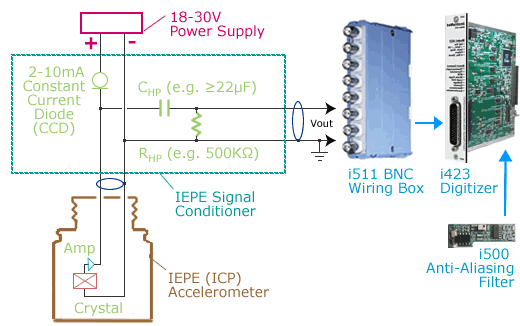
IEPE accelerometers contain a piezoelectric device and amplifier that
detects acceleration and converts it to voltage. IEPE stands for "Integrated Electronics Piezo Electric". Other proprietary names
for the same principle are ICP, CCLD, Isotron, Deltatron, Piezotron and others. This device is powered by a 18V to 30V
external power supply and constant current diode (CCD).
The result is an AC signal that sits on top of a DC bias voltage (e.g. 10V). The bias voltage is removed with a high pass filter (i.e. one resistor and one capacitor) and then feed into the
voltage input of a data acquisition system. The CCD and High Pass filter are
often considered to be the IEPE "signal conditioner", and are available from 3rd parties. The data acquisition system
cannot contain a multiplexor at its input since they pump current when
they switch and this interacts with the high pass filter;
therefore, one can attach it to an
i423 or
i100, yet not
i430/i420/i60x.
An i500
anti-aliasing filter daughterboard typically mounts on top of the i423 card to
remove frequencies in excess of half the sample rate,
as explained here.
The below illustration shows a typical IEPE Accelerometer configuration.
For more details, click here.
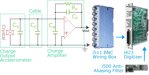
Charge Accelerometers output a charge proportional to acceleration. This charge is converted to a voltage via an external charge-to-voltage converter, available from 3rd parties. The charge is emitted from a crystal and pumps up a voltage across amplifier capacitor CF. A small amount of this charge leaks into error capacitances CS, CC, and CA (one would like these to be as small as possible). One typically attaches the output of the charge amplifier to an i423 card via an i511 BNC Wiring Box. An i500 anti-aliasing filter daughterboard typically mounts on top of the i423 card to remove frequencies in excess of half the sample rate, as explained here. The below illustration shows a typical Charge Output configuration. For more details, click here or here.
MEMS Accelerometers output a voltage proportional to acceleration. MEMS stands for "Micro-Electro-Mechanical Sensors" and these devices are often housed inside of a semiconductor IC (e.g. see Analog Devices MEMS devices). In some cases, one places several passive components between the MEMS device and the voltage measurement system for purposes of high or low pass filtering. If this is the case then one needs to attach to a data acquisition system that does not contain a multiplexor at its input since they pump current when they switch (which interacts with passive components). The i423 card and i51x wiring box satisfies this requirement and are therefore often used with MEMS sensors, as illustrated below. An i500 anti-aliasing filter daughterboard typically mounts on top of the i423 card to remove frequencies in excess of half the sample rate, as explained here.
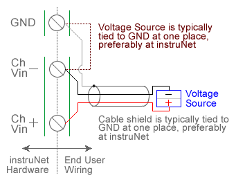
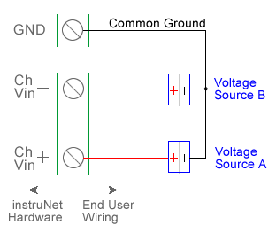
An Accelerometer is an external device that measures acceleration in "g" units. They contain an internal constant mA excitation current and provide a voltage output to the instruNet (i.e. instruNet does not provide excitation). instruNet connects directly to accelerometer sensors that output voltage and returns g units to the end user. For example, if a sensor experiences 19.6 meters-per-second-per-second acceleration (9.8m/s/s * 2.0 = 19.6), then the instruNet software will return "2.0" g. When one selects Accelerometer in the Sensor field, an interview leads the user through the setting up of the device. One enters parameters such as maximum and minimum acceleration (g units) and mV per g sensitivity as specified on the physical package label (e.g. one enters "0.002" if the package label specifies 2 mV/g). Accelerometers are wired either single-ended (SE) or differential (DI). If one uses SE, then the sensor must be wired as shown in the above SE diagram, and the Wiring software field must be set to Vin - GND. If one uses DI, then the sensor must be wired per the above DI diagram, and the Wiring field must be set to Vin+ - Vin-. instruNet calculates acceleration using the equations:
Vmeasure (V) = (Vin+ - Vin-) or (Vin - GND) GF (Vmeasure per g) is a fixed value that is specified by the user in the Constants Settings area (indirectly if set via the interview), whereas Vmeasure is measured in realtime by instruNet. To do an Accelerometer measurement, you must wire your sensor per the above diagram and then set up your software via the Interview process (started after selecting sensor type in Channel Setup dialog) or by manually running through the below steps: 1. Set the Sensor field in the Hardware settings area to Accelerometer. 2. Set the Measurement Range in the Hardware settings area. For details, click here. 3. Set the GF field in the Constants settings area to the sensors sensitivity in Vmeasure-per-g units. 4. Set the Vinit field in the Constants settings area to the voltage measured when the acceleration is 0g. This is used to calibrate the sensor when 0g is applied. 5. Set the Wiring field in the Hardware settings area to either Vin+ - Vin- (differential, figure a) or Vin - Gnd (single-ended, figure b). Click here if you need more guidance setting up the software, and click here if the measured value is not correct. 5, 10
|