Hidden
Hidden
Hidden
Hidden
Hidden
Hidden
Hidden
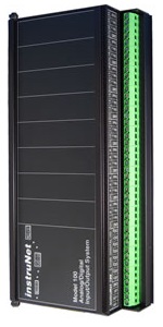
ANALOG VOLTAGE MEASUREMENT (VOLTS, A/D) The following instruNet hardware supports analog Voltage measurements:
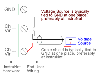
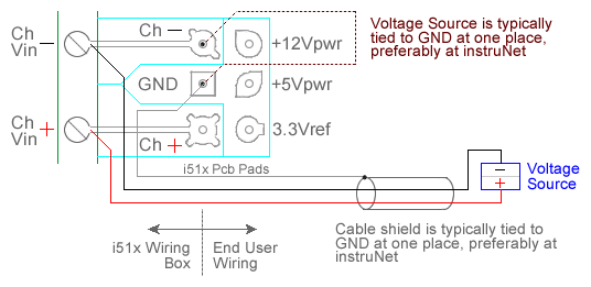
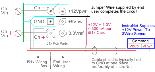
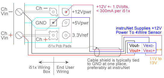
For quick setup instructions, click here. Single-Ended Setup Instructions This involves reading a voltage between the Vin+ (or Vin-) instruNet input terminal and the Gnd input terminal, as illustrated in the above single-ended (SE) wiring figures a/b/c. The Gnd terminal is typically tied to earth ground through the user's cable, the instruNet network cable, or an external power supply cable. Most amplifiers that supply a single-ended output signal have their grounds tied to earth ground via the power supply cable. instruNet channels, configured for "Voltage" measurement, return a value in units of Volts. The Vin+ and the Vin- screw terminals function identically when used to read
single-ended voltages (e.g. Ch1 corresponds to Vin+, and Ch2 corresponds to Vin- on the i42x/i43x/i60x). To do a Single-Ended Voltage measurement you must wire your sensor per the above diagram and then set up your software via the Interview process (started after selecting sensor type in Channel Setup dialog) by manually running through the below steps: 1. Set the Sensor field field in the Hardware settings area to Voltage. 2. Set the Wiring field in the Hardware settings area to Vin - GND (single-ended). 3. In most cases, the signal source is an electronic amplifier with a low source impedance (e.g. ≤ 200 ohms). However, if this is not the case and one is working with a multiplexor front end (e.g. i420, i430, i60x), then it is recommended that one specify the signal source impedance in the delta field, in ohms units. This causes the channel scanning to slow down sufficiently to accurately acquire the channel after switching. 4. Wire your voltage source per above single-ended figures a/b/c. Click here if you need more guidance setting up the software, and click here if the measured value is not correct. Differential Setup Instructions This involves reading a voltage between a pair of instruNet Vin+ and Vin- input terminals,
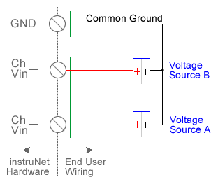
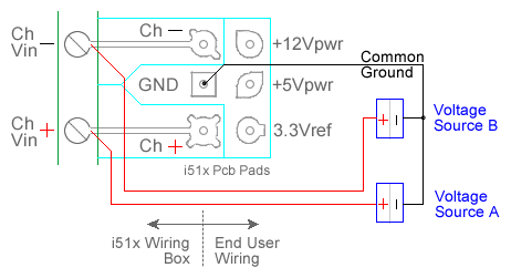
as illustrated in the above differential (DI) wiring figures j/k/l/m/n. The Gnd terminal is not used when connecting
a differential voltage source to instruNet; however, you must be careful to insure
that the voltage applied to the Vin+ or Vin- terminal does not exceed the
specified maximum (e.g. all Vin terminals on the i420/i430/i60x
must be kept between -10V and +10V, with respect to the Gnd terminal, in order to assure
accurate readings). Differential mode is preferable for applications involving
significant amounts of low frequency (< 5kHz) common mode noise that might result from long signal cables. instruNet channels, configured for "Voltage" measurement, return a value in units of Volts. To do a Differential Voltage measurement you must wire your sensor per the above diagram and then set up your software via the Interview process (started after selecting sensor type in Channel Setup dialog) or by manually running through the below steps: 1. Set the Sensor field field in the Hardware settings area to Voltage. 2. Set the Wiring field in the Hardware settings area to Vin+ - Vin- (differential). 3. In most cases, the signal source is an electronic amplifier with a low source impedance (e.g. ≤ 200 ohms). However, if this is not the case and one is working with a multiplexor front end (e.g. i420, i430, i60x), then it is recommended that one specify the signal source impedance in the delta field, in ohms units. This causes the channel scanning to slow down sufficiently to accurately acquire the channel after switching. 3. Wire your voltage source per above figure j/k/l/m/n. Click here if you need more guidance setting up the software, and click here if the measured value is not correct. 4. If your measured signal is noisy, try connecting a wire between the Vin- and GND terminals (to reduce common mode noise), and refer to footnote 5 for details on how to low pass filter the measured signal.
|