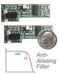
End user installs between 1 and 6 filter daughterboards onto each
i423
card, one daughterboard per channel
Maximum of 35 filtered channels per system
Sold in packages of two filters per product, each is 1.7 x 0.6 inches (4 x 2 cm)
i500 analog filter provides extremely low ±0.01dB maximum passband
ripple for Fin/Fc ≤ 0.5.
If one uses further
oversampling, digital filtering and
desampling; then passband ripple
is ±0.002dB for Fin/Fc ≤
0.8 due to the accuracy of a 30-pole digital filter.
i500 analog filter provides stopband attenuation of ≥ 76dB for Fin/Fc ≥ 3
4 different filter products, each with different cut off frequencies:
380Hz, 1KHz, 3.3KHz, 10KHz. However, further digital processing provides
other cutoff frequencies lower than these. For example,
with an i500 Fc=1KHz analog filter one can digitize at
ANY sample rate less than 2Ks/sec/channel and have a DIGITAL
low pass filter provide anti-aliasing.
For a summary of aliasing and why you might need an AFS filter, click
here.
i500 Product Summary
The instruNet
i4xx
card cage is available with 4, 8, 12 or 16 slots.
The first slot is used to house the
i41x
interface card and the 2nd slot
is used for the
i43x
a/d measurement card. One can populate the remaining
slots with
i423
cards. The i423 provides 6 signal conditioning amplifiers, one for each channel. These can measure voltages, and can also attach directly to common sensors such as
thermocouples and strain gages. Each channel on the i423 includes a socket
that attaches to a tiny optional 4 x 2 cm daughterboard. This is held in place with one
bolt
and is installed by the end user. There are four different i500 filter
daughters to choose from, each with a different cutoff frequency.
Yet optional further digital low pass filtering provides lower cutoff frequencies.
For example, one can digitize at 100s/sec/channel with the Fc=1KHz i500
analog filter and digitally filter at Fc=38.5Hz to get anti-aliased 100s/sec/ch data.
Internally the system would digitize at ≥ 6Ks/sec/ch and do digital processing to calculate
very accurate 100s/sec/ch data. This digital processing is done
in the background and the end user only needs to set one software
parameter called "Auto Afs" to enable it.
Analog & Digital Filtering via Auto Afs
There are two methods of implementing anti-aliasing with instruNet.
One method is to oversample, digitally filter, and then desample (Auto Afs ON). The other method
involves no oversampling and no digital filtering (Auto Afs OFF).
The end user enables Auto Afs with a parameter in the
Record Setup
dialog box. Both methods result in aliased free data. Auto Afs ON has several advantages:
digital processing provides ANY
low pass cutoff frequency (Fc) less than 77% of the i500 analog cutoff frequency;
where sample rate is 2.6 times this Fc
lower passband ripple
passband is larger with respect to sample rate
(i.e. sharper roll-off from digital filter)
The two Auto Afs options are described below:
1)
Auto Afs OFF (no digital filtering)
The table below summarizes Auto Afs OFF (no digital filtering,
no oversamping). "Sample Rate" refers to the number of points digitized
per channel in order to attenuate at least 76dB at the nyquist frequency (which
is what is needed to obtain fully anti-aliased data). "Passband (Hz)" is the frequency range of
the resulting data with ≤ ± 0.01dB of ripple (deviation from gain of 1.0),
where Fin/Fc ≤ 0.5.
"Max # of Channels" is the maximum number of
channels that one can digitize at this sample rate,
as limited by the i423 maximum
aggregate sample rate, which is documented here.
Also, the i312 power supply supports
up to 35 quantity i500 filtered channels in a card cage with six i423 cards.
#i500-380Hz
#i500-1KHz
#i500-3300Hz
#i500-10KHz
Parameter
380
1,000
3,300
10,000
i500 Analog Filter Fc (Hz)
2,304
6,000
19,800
60,000
Sample Rate (s/sec/ch)
1,152
3,000
9,900
30,000
Nyquist (Hz)
190
500
1,650
5,000
Passband (Hz)
35
13
4
1
Max # of Channels
2)
Auto Afs ON (oversample, digital filter, desample)
The below table summarizes operation when the Auto Afs feature is
ON (i.e. oversample, digitally filter, desample). "End User Data" refers to the
largest sample rate for aliased-free data and is set by the end user
in the Sample Rate field within the
Record Setup
dialog. The system internally samples faster (oversample). The Nyqust frequency is 50% of the End User
sample rate and the nyquist is 130% of the digital filter cutoff frequency
(Digital Filter Fc). The resulting Passband is 90% of the Digital Filter Fc. The ratio of the
internal oversample rate and the end user sample rate is an integer;
therefore not all sample rates are feasible. Subsequently, if Auto Afs does
not engage, try a slightly different sample rate.
#i500-380Hz
#i500-1KHz
#i500-3300Hz
#i500-10KHz
Parameter
380
1,000
3,300
10,000
i500 Analog Filter Fc (Hz)
≤ 777
≤ 2,022
≤ 6,673
≤ 20,222
End User Data (s/sec/ch)
≤ 388
≤ 1,011
≤ 3,337
≤ 10,111
Nyqust (Hz)
≤ 299
≤ 778
≤ 2,567
≤ 7,778
Digital Filter Fc
≤ 269
≤ 700
≤ 2,310
≤ 7,000
Passband (Hz)
35
13
4
1
Max # of Channels
List of Analog Filter Products
Below is a list of products, which are sold in packages of 2 filters per package. Each digitized channel, attached to a sensor, supports one filter daughterboard.
Product Model #
Fc Freq
Description
#iNet-500-380Hz
380 Hz
Package of 2 analog filter daughterboards (supports 2 independent channels), 8-Pole, Butterworth
#iNet-500-1KHz
1 KHz
"
#iNet-500-3300Hz
3.3 KHz
"
#iNet-500-10KHz
10 KHz
"
Signal Path
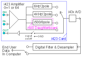
The diagram to the right shows the signal path when working with the i500 analog filter.
The signal first passes through the
i423
low noise amplifier which amplifies the
signal with a gain between 1 and 64. This gain is set by the end user via the
Measurement Range
parameter in the Hardware channel setting area.
The signal then passes through one of the following: i500 8-pole analog filter,
internal i423
6Hz/2pole filter, internal i423
4KHz/2pole filter, or no analog filter.
The filter is selected by the end user with the
Low Pass Filter
parameter in the Hardware channel setting area. After this, the signal is optionally further
processed with a 30-pole digital filter and desampler. To enable this digital
filter, one must set the end user
Sample Rate
parameter (samples-per-second-per-channel)
to a value that is less than 2 times the i500 Fc frequency
(e.g. < 2Ks/sec/ch with i500-1KHz)
and then set the Auto Afs parameter in the
Record Setup
dialog box to On.
To verify that it is set up properly, select
Digitize Channels Report
under Setup in the menubar.
Filter Output Available Electrically at Hd44 Connector Pin
Notice the above "Signal Path" illustration has an
OUT pin along the left edge. Filter
outputs are available electrically at i423
Hd44 connector pins 17 through 22.
These are short circuit protected against ±12Volts power on or off; have a drive capability
of 3mA and 10K pF via an internal operational amplifier;
and have a maximum output working voltage of ±5Volts. These buffered outputs are normally
off (0Volts output), and remain off until the end user has turned them on. This can be done by setting
Channels #17...22 to ON from within instruNet World software
(i.e. click on i423 Ch17..22 in NETWORK page and set Amplifier Output to ON),
or writing ON (1=on, 2=off) to those channel addresses
via software. The advantage of keeping them off is they are less likely to couple into input signals
within the end user's cable.
One can use the output pin without digitizing by running the instruNet software
and setting the following parameters, as described here
(except for enabling for digitize).
Low Pass Filter Theory of Operation
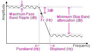
The figure to the right describes a low pass filter.
In summary, a low pass filter passes low frequencies and attenuates
high frequencies. The transition from the passband to the stopband
occurs in the vicinity of the cutoff frequency, commonly referred
to as "Fc" in units of Hz. It is here that the signal is attenuated 3dB,
which corresponds to a 70% attenuation in amplitude voltage.
For example, if you input a 1KHz 10Vpp (volts peak-to-peak)
sine wave into a filter with a 1KHz Fc, then the output will be
1KHz 7Vpp. Power is porportional to the square of the Voltage,
therefore a 70% attenuation in voltage is associated
with a 50% (70% * 70%) attenuation in power.
Passband Ripple
In the passband, a perfect filter has a gain of 1.0, which is the same as 0 dB.
Yet real filters vary slightly from 1.0 and this deviation
is sometimes referred to as "passband ripple", as illustrated in the above figure.
The maximum ripple is specified
in the below table for both the i500 analog filter and a
30-pole digital filter which might follow the i500 analog filter.
Frequency (Fin/Fc)
i500 ANALOG Filter Max Ripple (Auto Afs OFF, 8-poles)
DIGITAL Filter Max Ripple
(Auto Afs ON, 30-poles)
0.9
-8.0 ± 4.0% (-0.7 ±0.4 dB)
-0.1 ± 0.03% (-0.008 ±0.003 dB)
0.8
-1.4 ± 0.8% (-0.12 ±0.08 dB)
±0.02% (±0.002 dB)
0.5
±0.1% (±0.01 dB)
±0.02% (±0.002 dB)
≤ 0.3
±0.05% (±0.005 dB)
±0.02% (±0.002 dB)
For example, if one inputs a 400Hz sine wave with
amplitude 1Vpp (Volts between top and bottom of sine,
peak-to-peak) into an i500-1KHz filter, then the digitize signal
would be a 400Hz sine with an amplitude between
0.999Vpp and 1.001Vpp (i.e. 0.1% ripple). And in the
frequency range ≤ 300Hz; the output would be
between 0.9995Vpp and 1.0005Vpp.
A typical 30-pole digital filter often has a variation
less than 1 LSB (least significant bit)
of the A/D (analog to digital) converter, which means
it is close to perfect. The reason
digital filters are more accurate is the numerical
coefficients used to implement
them are accurate to 7 decimals (e.g. 0.00001%) and the
resistors and capactors in analog filters are typically accurate to 1%.
A
potentiometer on the i500 is
set at the factory and is used to tune errors from
resistors and capacitors. This works to some extent, yet not to the point
of making a perfect filter. One reason of which is that resistors and capacitors vary
slightly with temperature and with time ("stability"). Therefore setting a
potentiometer in the factory while the filter is at one temperature
will see a little variation later when the filter in the field
is at a slightly different temperature.
All i500 analog filter daughterboards uses NPO/COG capacitors
that are accurate to approximately 1% in initial value, and drift very
little with temperature (e.g. 30ppm/C); and are therefore very accurate.
A common problem in filter design is lower frequency filters
(e.g. < 100Hz Fc) need larger capacitors and larger capacitors
are often not available in accurate and stable materials.
The i500 filter product family deals with this by providing
the i500-380Hz lowest Fc filter (which uses accurate capacitors)
and then provides lower Fc's to the end user with digital
filtering and desampling that follows the analog filtering. Therefore, the
end user can enjoy extremely accurate data (e.g. < ±0.002 dB ripple)
at lower Fc frequencies.
Stopband Attenuation
The stopband involves frequencies in excess of the cutoff frequency.
Stopband minimum attenuation for both the i500 8-pole analog filter
and 30 pole digital filter (which might follow i500) are shown in the below table.
Frequency (Fin/Fc)
i500 ANALOG Filter Min Attn
(Auto Afs OFF, 8-poles)
DIGITAL Filter Min Attn (Auto Afs ON, 30-poles)
1.0
70% (-3 dB)
70% (-3 dB)
1.1
45% (-7 dB)
4% (-28 dB)
1.2
25% (-12 dB)
0.3% (-50 dB)
1.3
14% (-17 dB)
0.02% (-72 dB)
1.5
5% (-26 dB)
< 0.01% (-80 dB)
2.0
0.5% (-46 dB)
< 0.01% (-80 dB)
≥ 3.0
< 0.015% (-76 dB)
< 0.01% (-80 dB)
For example, if you digitize at 200s/sec/channel (100Hz nyquist)
with a i500-1KHz analog filter and Auto Afs enabled, then the instruNet system will
internally digitize faster (e.g. ≥ 6Ks/sec/ch), pass the signal
through the i500 analog filter (Fc = 1KHz), run a 30-pole digital
filter (Fc = 76Hz) and provide > 72dB of attenuation at
the 100Hz nyquist frequency (1.3 * 76 Hz = 100 Hz). In this example,
one would have < ±0.02% (±0.002 dB) passband
ripple for frequencies < 61Hz (0.8 * 76Hz = 61Hz).
The following steps are required to set up an i500 low pass filter:
Physically install your i500 hardware daughterboards, as described
here.
Make sure you are working with instruNet DLL file "iNet32.dll" version ≥ 3.3.4.4. To check your version, run instruNet World software and select
ABOUT in the HELP
menu. To upgrade to a newer iNet32.dll file, free of charge, click
here.
Run instruNet World software and set up your channels without low pass filtering.
Digitize
in the Record page and make sure your channels are set up properly. Save your settings
by pressing the SAVE button in the NETWORK page (not the RECORD page).
For
each channel with an i500 filter, set the
Low Pass Filter (Hz)
parameter to "i500-xx Hz", as shown to the right. This will cause the signal to pass through
the 8-pole i500 analog filter after being amplified by the i423 signal conditioning amplifier.
You need to do this independent of whether or not you are enabling Auto Afs.
Set
the Auto Afs parameter in the
Record Setup
dialog box to On, as shown to the right.
This will enable the more accurate digital processing, if possible.
If it is not possible (e.g. your requested sample rate is too high),
then the digital processing will not occur. It is recommended that this
always be ON when working with i500 filters.
Turn
off
Integration
for all channels that are
digitizing. In other words, set Integration to 0 seconds, as shown to the right.
This is very important since Integration directly reduces
maximum oversampling sample rate, as noted
here.
Set your
Sample Rate
(samples-per-second-per-channel) in the
Record Setup dialog box. This is not the oversample rate. This is the sample rate of the
data that is returned to the end user. The end user never sees the oversampled data.
Select
Digitize Channels Report
under Setup to see if your
channels are set up as desired. Focus on the "Aliasing Occurs Here"
column. You want to see "No Aliasing". If you do not,
then your anti-aliasing is not set up properly; in which case, see
Debugging
below.
Try Digitizing in the Record page and view your resulting waveforms.
For details on how to do this, click
here.
If you want to do more serious testing with a function generator, click
here.
Press the SAVE button in the NETWORK page (not RECORD page) to save your settings.
If you want to further test and/or debug,
click here.
i500 Filter Hardware Installation
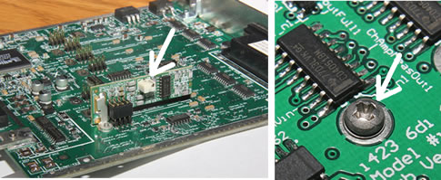
The i500 filter daughterboard bolts to the
i423
card, one daughterboard per channel, as shown in the
below photo.
When installing the i500, make sure the
2-56 bolt
is snug. Obviously, one needs to remove the i423 card before installing the i500 daughterboard.
The i423 sockets are labeled "Ch 1", "Ch3", etc.
i500 Considerations
After you turn
Auto AfsOn, the system checks if it can internally
digitize at a rate faster than the end user requested sample rate. If so,
it oversamples (internally digitizes faster), digitally filters, and then desamples.
If not, it digitizes
normally. To learn more about this for a specific setup,
select Digitize Channels Report under Setup.
The maximum aggregate (all channels) sample rate on
the i423 is approximately 80ks/sec
when integration is set to 0 seconds.
This varies slightly with smaller voltage ranges, as noted here.
This limits the number of channels you can
digitize when oversampling, digital filtering, and desampling.
The internal oversample rate cannot exceed this ~80ks/sec aggregate limitation.
The end user waveform can be at any sample rate less than this and is set
in the Record Setup dialog box via the
end user data Sample Rate
parameter. The Digitize Channel Report shows the oversample rate in the "Oversample Rate"
column; and shows the end user sample rate in the "Sample Rate" column.
80Ks/sec aggregate means that you can digitize 2 channels at 40K each,
3 at 26K each, 4 at 20K each, etc.
After turning On the
Auto Afs parameter,
the system will oversample, digital filter, and desample if possible. To see
if this is actually happening (i.e. auto afs is engaging), select
Digitize Channels Report and look for
"Auto afs implemented OK" above the table. If you see this comment,
then the 30-pole digital filter is working to return very accurate data.
One can turn On the
Auto Afs parameter
with no i500 analog filters installed,
and this will cause the system to still oversample, digitally filter,
and desample; to reduce aliasing. To help further reduce aliasing,
one can turn ON the i423 internal 4KHz/2pole or 6Hz/2pole analog
Low Pass Filter.
To see the effect of your set up, select Digitize Channels Report under Setup.
In order to digitize with the i500 analog filter, you need an
i423 card, an
i43x a/d card,
and an i41x interface card.
The later two cards (i41x, i43x) are included with the
i555 product.
One might also want an i51x
wiring box affixed to the i423 card.
After pressing the START
digitize button, the digital
filter outputs might appear erradict for a short duration (e.g. 50mSec with Fc=1KHz);
due to not having past data.
Analog and digital filters often induce delays. To see this, digitize the
same signal with 2 channels (e.g. jumper wire connects two inputs),
where one channel has an i500 filter and the
other does not (or turn one i500
off).
Then look at both waveforms in the Record page
and notice one is horizontally shifted with respect to the other.
Analog Trigger
initiates the start of a digitization
and looks at the waveform after the analog filter yet before
before any digital filters.
One cannot simultaneously digitize from voltage input channels and output to d/a channels while doing Auto Afs.
The Auto Afs digital filter is not related to the end user controlled
Digital Filters.
These two operate independently and in series.
After setting up your channels for anti-aliasing,
as described here, select
Digitize Channels Report
under Setup in the menubar to learn about your setup.
Make sure that the "Alias Occurs Here" column shows
"No Aliasing". If you do not see this, then check each step
in Software Setup. Do you have
Integration
turned off for channels enabled for
digitizing (you want it set to 0 seconds)? Did you remember
to enable your i500
Analog Filter?
Are you digitizing from channels that have an
i500 analog filter daughterboard physically installed?
When Auto Afs is engaged, the ratio of the internal oversample
rate and the end user data sample rate
is always an integer; therefore not all sample rates are feasible. Subsequently,
if Auto Afs does not engage, try a slightly different sample rate.
When doing Auto Afs, there is an end user data sample rate and an over sample rate.
Lets call the ratio between these two X.
Also, for each channel, there is an end user data RAM buffer and an over sample RAM buffer of size (Points-per-Scan) and (Points-per-Scan * X) respectively. Recall that end user Points-per-Scan and Sample Rate (s/sec/ch) are set in the Record Setup dialog box. If Points-per-Scan is
big (e.g. ≥ 100M) then your over sample RAM buffer will be very big and you might
get an "out of memory" alert when you
start digitizing. To see the over sample rate, refer to the "AFS Oversample Rate"
column in the
Digitize Channels Report .
If the i2x0 controller SWITCHING parameter is set to ACCURATE (instead of FAST), then the
controller will switch between channels more slowly
and maximum total aggregate sample rate is ~30ks/sec instead of ~166Ks/sec.
To access the SWITCHING parameter in instruNet World software, press the SETUP button in the
RECORD page and then press the TIMING button.
To access the the SWITCHING parameter in DASYLab software,
press the SET GLOBAL INSTRUNET PARAMETERS button within the voltage input icon.
The default setting is ACCURATE in DASYLab and FAST in all other cases.
Input a sine wave
(e.g. from an external function generator) at different
frequencies while digitizing
anti-aliased data and note
digitized amplitude as a function of frequency.
The sine should appear in the Record page if its frequency is
less than approximately 40% of the sample rate;
and should appear as 0 Volts DC if its frequency is higher.
Try this again with the i500
Low Pass Filter
turned off and note that higher frequencies now appear
fully intact, or they appear at a lower frequency (i.e. they alias)
yet at an amplitude similar to the input signal.
Many of the older (≤ 2010 era) low cost (≤ $300)
function generators output several milliVolts of
both low and high frequency noise/harmonics,
and this is added to the intendend output signal. If you filter out the
intended signal and then look at the result, you might see this "error" signal
that is coming from your (deficient) function generator.
The lowest cost ≥ 2011
Rigol function generators
provide a
clean signal at reasonable cost.
Digitize Channels Report
After setting up the system, one can easily learn more about
bandwidth and aliasing by selecting
"Digitize Channels Report" under Setup in the menubar, as illustrated to the right.
This prints a table that
describes channels
enabled
for digitizing.
Auto Afs Engage Indicators
If Auto Afs is turned On and the setup is sufficient for
oversampling, digital filtering, and desamping; then
"Auto afs implemented OK" will be shown above the digitize channel report table and "Afs On" will be shown to the right of the PRINT button in the RECORD
page while digitizing. These two indicators communicate that auto afs has engaged and that the 30-pole digital filter is returning very accurate data.
Channel Report from DASYLab Software
To access this report from DASYLab software, click OPEN INSTRUNET WORLD WINDOW from within
the voltage input icon; and then select "Digitize Channels Report" under Setup.
Digitize Channel Report Columns
The columns of the Digitize Channel Report table are described below.
Column
Description
Sample Rate (s/sec)
Sample Rate per channel
in samples-per-second-per-channel units. This is end user
data, after any oversampling/filtering/desamping.
Nyquist (Hz)
Bandwidth of end user data, in units of Hertz.
This is always 50% of the sample rate.
End User Bandwidth (Hz)
Bandwidth of end user data, after it has been filtered.
If Auto Afs is ON, this is 90% of the Digital Filter
cutoff frequency (Fc).
Aliasing Occurs Here
If there is no aliasing, then "No Aliasing" is shown; otherwise, the
frequency at which aliasing begins is displayed.
Analog Bandwidth (Hz)
Bandwidth of signal conditioning amplifier and analog filter.
Analog Filter (Hz)
If an analog filter is enabled, the cutoff frequency is shown;
otherwise, "Off" is displayed.
AFS Digital Filter Passband (Hz)
If Auto Afs is ON, this is 90% of the Digital Filter Fc. It is also the maximum frequency with
a tiny amount of passband ripple.
AFS Oversample Rate (s/sec)
If Auto Afs is ON, this is the internal oversample rate
in units of samples-per-second-per-channel.
Integration Time (mSec)
Amount of Integration
time in units of mSec.
If integration is off (i.e. 0 sec) then "No Integ" is displayed.