Hidden
Hidden
Hidden
Hidden
Hidden
Hidden
Hidden
ANALOG RESISTANCE MEASUREMENT (OHMS) The following instruNet hardware supports Resistance Measurements with the help of an external shunt resistor:
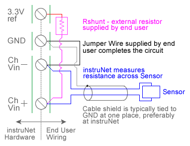
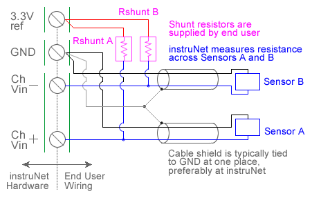
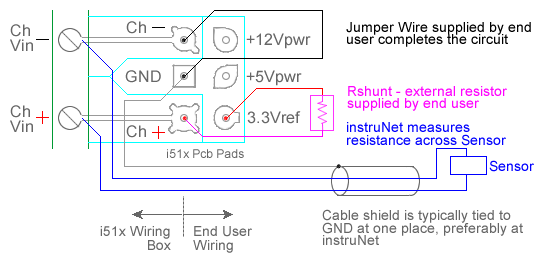
For quick setup instructions, click here. Resistance measurement using a voltage divider involves connecting a resistor of unknown value in series with an external user supplied shunt resistor of known value, applying a voltage across the voltage divider circuit, and measuring the voltage across Runknown (i.e. the external sensor), as illustrated in the above figures. The voltage across Runknown is measured between a pair of instruNet Vin+ and Vin- input terminals while the excitation voltage is supplied by the instruNet Vout terminal. instruNet then calculates the value of Runknown using the following equation, and returns a value in "ohms" units: Runknown (Ohms) = Rshunt * (Vin+ - Vin-) / ((Vin+ - Vin-) - Vout) To do a Resistance measurement using a Voltage Divider, you must wire your sensor per the above diagram and then set up your software via the Interview process (started after selecting sensor type in Channel Setup dialog) or by manually running through the below steps: 1. Set the Sensor field in the Hardware settings area to Resistance. 2. Set the Wiring field in the Hardware settings area to Voltage Divider. 3. Set the Rshunt field in the Constants settings area to the value of your external user supplied Rshunt resistor, in ohms units. 1, 3, 6 4. If working with hardware that has variable internal excitation (e.g. i100 ± 5V), then set the Vout field in the Constants settings area to the desired excitation voltage 2, 11. Alternatively, if applying an external excitation voltage, enter -Ro value in the Ro edit field (e.g. -100 instead of 100 ohms) to tell the software that the excitation is external, and then enter the external excitation voltage in the Vout field. 5. Set the Measurement Range in the Hardware settings area. For details, click here. 6. Wire your sensor per the above figures. Click here if you need more guidance setting up the software, and click here if the measured value is not correct 10. If you want a detailed report on your setup, press the Sensor Report button in the Channel Setup dialog. Resistance Measurement using Bridge Circuit An alternative to the above technique is to use a Bridge circuit to measure small resistance changes from a nominal value (e.g. accurately measure a device that ranges between 340 and 360 Ω). Resistance measurement using a bridge circuit involves connecting a resistor of unknown value as one leg of a full-bridge circuit, applying a voltage across the bridge, and measuring the voltage across the two intermediate nodes. The intermediate node voltage is measured between a pair of instruNet Vin+ and Vin- input terminals while the bridge excitation voltage is supplied either by the instruNet or by an external voltage source. In the below figure, Runknown is a resistor whose value is being measured and Ro is a similar valued resistor of known value. This technique is only accurate if Runknown stays in the range of Ro , ± 50%. If you need to measure a resistance with more range, please use the Resistance Measurement using a Voltage Divider, described above. instruNet calculates the value of Runknown using the following equation, and returns a value in "ohms" units: Runknown (ohms)
To do a Resistance measurement using a Bridge circuit you must: 1. Set the Sensor field in the Hardware settings area to Resistance. 2. Set the Wiring field in the Hardware settings area to Bridge. 3. Set the Ro field in the Constants settings area to the value of one Ro bridge completion resistor, in ohms units. 1, 3, 4 4. Set the Measurement Range in the Hardware settings area. For details, click here. 5. If working with hardware that has variable internal excitation (e.g. i100 ± 5V), then set the Vout field in the Constants settings area to the desired excitation voltage 2, 11. Alternatively, if applying an external excitation voltage, enter -Ro value in the Ro edit field (e.g. -100 instead of 100 ohms) to tell the software that the excitation is external, and then enter the external excitation voltage in the Vout field. 6. Wire your voltage source per the above Bridge figure. Click here if you need more guidance setting up the software, and click here if the measured value is not correct. 5, 10
|