Hidden
Hidden
Hidden
Hidden
Hidden
Hidden
Hidden
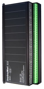
ANALOG VOLTAGE VIN/VOUT RATIO MEASUREMENT (V/V) The following instruNet hardware supports voltage ratio measurements, where it returns the ratio of an excitation voltage and a measured voltage:
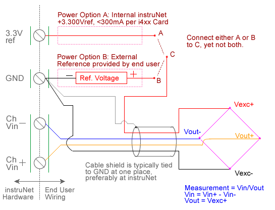
Voltage ratio measurement involves measuring the ratio of the voltage measured across a device (e.g. a bridge) to the excitation voltage applied to the device, as illustrated in the above figure. This involves applying a voltage across the device and measuring the voltage across the two intermediate nodes via a pair of instruNet Vin+ and Vin- input terminals. The excitation voltage for the device is supplied either by instruNet or by an external voltage source. instruNet calculates the ratio, returning "Volts/Volts" engineering units, using the equations:
Vratio (V/V) = Measurement = Vin / Vout Vinit and Vout are fixed values that are specified by the user in the Constants Settings area, whereas (Vin+ - Vin-) are measured in realtime by instruNet. For more details, please see Maximizing Strain Gage Accuracy, Load Cells, and Voltage Ratio Measurements. To do Voltage ratio measurement one must: 1. Set the Sensor field in the Hardware settings area to Voltage. 2. Set the Wiring field in the Hardware settings area to Bridge. 3. Set the Ro field in the Constants settings area to the value of one Ro bridge resistor (i.e. or approx resistance across the device), in ohms units. 1, 3 4. If working with hardware that has variable internal excitation (e.g. i100 ± 5V), then set the Vout field in the Constants settings area to the desired excitation voltage 2, 11. Alternatively, if applying an external excitation voltage, enter -Ro value in the Ro edit field (e.g. -100 instead of 100 ohms) to tell the software that the excitation is external, and then enter the external excitation voltage in the Vout field. 5. Set the Vinit field in the Constants settings area to the voltage measured when the bridge is not stimulated, in Volts units (to null the bridge). 8 6. Wire your voltage source per the above figure. Click here for a review of the instruNet sensor software, and click here if the measured value is not correct. 5, 10 7. To eliminate susceptibility to RFI noise with the i100 (not with the i42x/i43x/i60x 12), it may be necessary to place a capacitor between the Vin+ and Vin- screw terminals, and between the Vin- and Gnd screw terminals, as noted in Maximizing Strain Gage Accuracy. Typical values are 0.01uF. Field Settings Summary The following summarized the settings used with voltage ratio experiments.
|