Hidden
Hidden
Hidden
Hidden
Hidden
Hidden
Hidden
LOAD CELL MEASUREMENT (e.g. Kg, LBs)
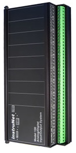
The following instruNet hardware supports Load Cell force measurements (i.e. measures Kg or LBs force):
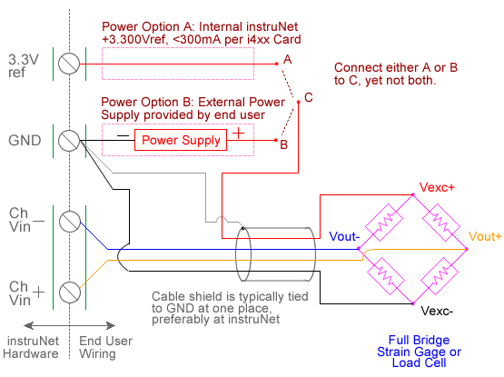
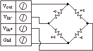
For quick setup instructions, click here. A load cell is an external device similar to a strain gage that measures force in Kg or LBs units. The instruNet hardware connects directly to load cells by providing an excitation voltage and returning Kg or LBs units to the end user. When one selects Load Cell in the Sensor field field, an interview leads the user through the setting up of the device. One enters parameters such as device resistance (ohms), excitation voltage specified on package label (V), maximum force (Kg or LB) at specified excitation voltage, and mV/V sensitivity (e.g. one enters "2" if the package label specifies 2mV/V). Load cells are set up in a bridge circuit where a voltage is applied across the bridge, and the voltage across the two intermediate bridge nodes is measured via a pair of instruNet Vin+ and Vin- input terminals. The excitation voltage for the bridge is supplied either by instruNet hardware or by an external voltage source. If you are not sure which to use, click here. instruNet calculates the force using the equations:
Vratio (V/V) = ((Vin+ - Vin-) - Vinit) / Vout The user either manually specifies the following fixed values in the Constants settings area or automatically via an interview process:
Ro - bridge resistance in ohms For more details, please see Maximizing Strain Gage Accuracy and Voltage Ratio Measurements. Make sure you are using instruNet software version ≥ 3.4.0.5 (i.e. file "iNet32.dll"). To check your version, select ABOUT in the instruNet World HELP menu; and to update for free, click here. At any time one can balance all gages (i.e. one point zero calibration of all load cells and strain gages) by applying 0 force to all gages and then selecting "Balance Gages" in the instruNet World "Hardware" menu. This causes instruNet to read 0 when 0 force is applied. To do a Load Cell measurement, you must wire your sensor per the above diagram and then set up your software via the Interview process (started after selecting sensor type in Channel Setup dialog) or by manually running through the below steps: 0. Make sure you are using instruNet software version ≥ 3.4.0.5 (i.e. file "iNet32.dll"). To check your version, select ABOUT in the instruNet World HELP menu; and to update for free, click here. 1. Set the Sensor field field in the Hardware settings area to Load Cell. 2. Set the Measurement Range in the Hardware settings area. For details, click here. 3. Set the Ro field in the Constants settings area to the value of one Ro bridge completion resistor (as specfied in load cell package label or datasheet), in ohms units. 3, 4 4. Set the GF field in the Constants settings area to the sensors sensitivity in VoltsMeasured-per-VoltsExcitation-per-Kg units (also noted in load cell datasheet). 5. If working with hardware that has variable internal excitation (e.g. i100 ± 5V), then set the Vout field in the Constants settings area to the desired excitation voltage 2, 11. Alternatively, if applying an external excitation voltage, enter -Ro value in the Ro edit field (e.g. -350 instead of 350 ohms) to tell the software that the excitation is external, and then enter the external excitation voltage in the Vout field. For more information on excitation, see 10V External vs. 3.3V Internal. 6. Set the Vinit field in the Constants settings area to the voltage measured when 0 force is applied, in Volts units. 8 7. Set the Wiring field in the Hardware settings area to Bridge. 8. Capacitors across the i100 (not with the i420/i430/i60x 12) voltage input terminals are highly recommended for reducing errors caused by RFI. With 350ohm sensors, 0.1uF caps create a low pass filter at 4KHz [4K = 1 / (6.28 * 350 * .1e-6)], and are ideal at minimizing RFI effects. 9. Wire your voltage source per the above figures. Click here if you need more guidance setting up the software, click here for information on how to calibrate your sensor, and click here if the measured value is not correct. 5, 10
|