Hidden
Hidden
Hidden
Hidden
Hidden
Hidden
Hidden
ANALOG CURRENT MEASUREMENT (e.g. 0-20mA) The following instruNet hardware supports analog Current measurements:
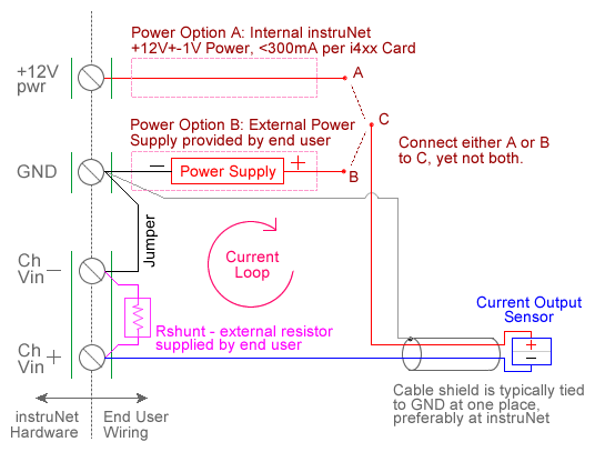
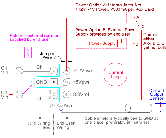
For quick setup instructions, click here. Current measurement involves reading the voltage across an external user supplied shunt resistor, to which a current source is connected, as illustrated above. The voltage is measured between a pair of instruNet Vin+ and Vin- input terminals. instruNet then calculates the current through the shunt resistor using the following equation, and returns a value in "Amps" units: current (Amps) = (Vin+ - Vin-) / Rshunt Shunt resistor values are typically chosen to cause a large voltage (several volts maximum) to be measured by instruNet, without saturating the current source (i.e. exceeding its maximum output voltage), and without heating up the resistor significantly to cause its resistance to change 1. If the Rshunt value is low, then the voltage across it is low, and this decreases the signal to noise ratio of the measured signal. Also, Rshunt must be selected such that the voltage across it does not exceed the instruNet maximum input voltage (e.g. ±5V with the i423). Due to these limitations, instruNet might not let you set some of the fields too high or too low. To do a Current measurement you must wire your sensor per the above diagram and then set up your software via the Interview process (started after selecting sensor type in Channel Setup dialog) or by manually running through the below steps: 1. Set the Sensor field in the Hardware settings area to Current. 2. Set the Wiring field in the Hardware settings area to Shunt Resistor DI (DI = differential). 3. Set the Rshunt field in the Constants settings area to the value of your external user supplied Rshunt resistor, in ohms units. 1, 3 4. Set the Measurement Range in the Hardware settings area. For details, click here. 5. Wire your current source per above figure. Click here if you need more guidance setting up the software, and click here if the measured value is not correct. 6. If your measured signal is noisy refer to footnote 5 for details on how to low pass filter the measured signal; also, if your current source is fully isolated from GND, connecting a 1K ohm (or wire) between the Vin- and GND terminals might reduce common mode noise.
|