Hidden Hidden Hidden Hidden


QUADRATURE SENSOR MEASUREMENT (± ticks)
APPLICATIONS > POSITION MEASUREMENT >

Measurement Hardware

The following instruNet hardware supports measurements from quadrature sensors:

i200 Controller PCI Card


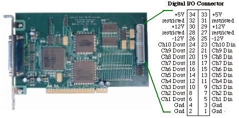
Quadrature Measurement with the iNet-200 PCI Card

Overview
The Model i200 (not 230) instruNet PCI Controller board has 5 digital input/output channel pairs, each of which can return the 4x position of a quadrature sensor with a ±32K counter. Connect wire A to Channel N, connect wire B to Channel N+1, and program Channel N for Quadrature, and away you go. For details on how to use the i200 counter/timer channels, click here; and for specifications, click here.

Limitations
High speed >1Ks/sec/ch digitizing of analog signals by the instruNet Controller ties up the i200 dsp processor, and therefore inhibits it from doing the following during that time: pulse counter, output a specific number of clock pulses, period measurement, and frequency measurement.

Wiring to the i200
Quadrature sensors have 2 output channels, often labeled "A" and "B". These are connected to two consecutive iNet-200 timer input channels, where A is routed to channel N, and B to N+1. Sometimes, the detectors will output two signals that are opposites of each other (one is high when the other is low, and visa-versa). These are sometimes labeled A and A'. With the instruNet 200, it is only necessary to connect one side (e.g. A) to the iNet-200. If the cable between the quadrature sensor and the iNet-200 is long (e.g. >30meters), then one might need to run the A/A' signals into an RS-422 receiver IC's (e.g. AM26C32) near the iNet-200, and then route the output of this IC to the iNet-200. This IC converts "digital differential" to TTL. TTL is not designed to transmit for long distances, where as differential digital RS-422 can support up to 1000 meters.

Software Setup
In instruNet World, click on the iNet-200 Timer channel connected to the A detector (the B channel is ignored), select the "Timer" Settings area, set the Function field to "Quadrature", close the dialog, and then observe the value of that channel as you move your sensor. The iNet-200 provides 4x encoding, which means it counts the pulse edges from both detectors, not each cycle to give you 4 counts per pulse. For example, if your linear sensor puts out 200 pulses per inch, and you pull the string out 1 inch, the computer should report 800. To reset the iNet-200 counter, one could set the Function field to Digital Input and then back to Quadrature, or set the Mode to "No Wait and Reset" and then back to "Wait & Continue". The iNet-200 quadrature counters have a -32767 to +32787 range, and roll over when they hit these bounds (e.g. with 800 counts per inch, the iNet-200 supports 41 inches prior to rollover).

DasyLab Software
Use the "Input Module" icon to connect to the iNet-200 Timer channel and set up the channel as described above. The measurement will be made at the end of a block. If you want your quadrature reading synchronized with your analog input icons, set your block size to 1.

Theory of Operation

What is a Quadrature Sensor?
Quadrature sensors are used to measure the position of a rotating shaft, or the linear position of an object moving back and forth along a line. These sensors are very common in industry, since rotation and linear position are two common parameters. For example, the auto industry uses quadrature sensors to monitor the position of rotating parts in an engine.

Quadrature Measurements
Quadrature sensors consist of a light source and a light detector separated by a small slotted wheel on a rotating shaft. As the shaft rotates, pulses of light illuminate the detector. Consequently, the detector puts out a digital TTL pulse each time a slot passes. Typical sensors have 60 slots per wheel. The detector pulses are counted by a quadrature encoder (e.g. iNet-200), which can in turn resolve the amount the shaft has rotated. To measure linear position, a string is wrapped around the shaft under spring tension, and one can pull the string off the shaft (like a string on a yo-yo), causing the shaft to rotate. When the string is released, the spring causes the shaft to retract back into its original position, with the string wrapped around it. This contraption can be used to accurately detect a position along a line, since the amount the string extends is porportional to the amount the shaft has rotated. Typical linear quadrature sensors can resolve position accurate to 0.1mm (.005 inches) in the 0 to 1.0 meter range. All quadrature sensors have two slotted wheels and two light detectors, to detect direction in addition to change. The wheels are out of phase, such that only one light detector is illuminated at a time. If the string on the shaft moves back and forth, one needs to count both up and down to keep track of its position. Therefore, each quadrature sensor consumes two instruNet-200 timer input channels. In summary, quadrature sensors are wonderful since they are extremely simple in their design, and are very precise.