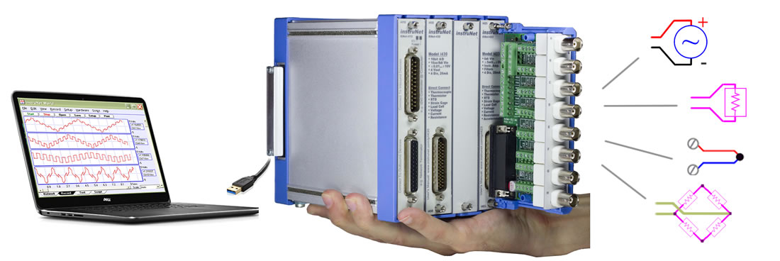
Thermocouple

Strain Gage

Thermistor

Thermistor

Volts

Current

Resistance

Load Cell
|
Connect Sensors to Computer via USB Data Acquisition System
i4xx Series Data Acquisition Cards
The table below shows which sensors directly connect to each hardware product. The numbers in the table refer to number of channels. The following sensors require an external shunt resistor: RTD, thermistor, resistance measurement, current measurement, ¼ bridge strain gage, and ½ bridge strain gage. Thermocouple sensors require an i510 Wiring Box attached to the i4xx card. In order to do voltage measurement, one needs at least one i430 A/D card. One only needs one i43x a/d card per card cage.
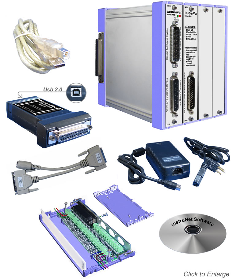
Analog and Digital I/O Cards instruNet i4xx cards are installed by the end user into an instruNet card cage that is 4, 8, 12 or 16 slots wide. Each card is 13 x 2.5 x 13 cm in size. Below is a list of available cards.
instruNet includes software to interrogate, test, configure, and do I/O with all network channels. This includes an application program called "instruNet World" and interfaces to Visual Basic, C, and C++. instruNet software can configure all I/O channels, store your settings, view digitized data in real time, stream data to disk, and scroll through your waveform post-acquisition. instruNet software runs on Windows computers.
Why is instruNet Better Than Other Systems?
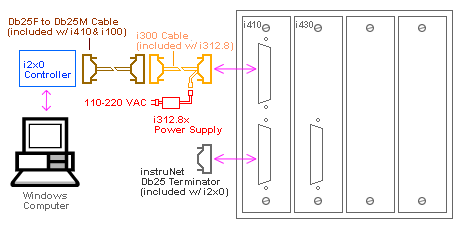
Low Cost Card Cage Each instruNet Network is controlled by an instruNet i240 DSP controller card that attaches to a Microsoft 32bit or 64bit Windows = Xp Sp3, Vista, 7 or 8 computer via High Speed USB 2.0 at 480mbit/sec. Each i240 Controller is an independent computer in itself that utilizes a powerful 32-bit DSP processor and onboard RAM to control all aspects of data acquisition along its network. All real-time tasks are off-loaded to this processor, therefore the host computer is not burdened with real-time issues. Each instruNet network supports up to 4 instruNet iNET-400 card cages.
The following table shows maximum aggregate sample rates for an i240 USB controller attached to an i4xx Card Cage. To calculate the sample rate for each channel, divide by the number of channels attached to the i240 controller. For example, if the maximum aggregate sample rate is 166Ksamples/sec/controller, and you digitize 4 channels, then you could digitize each channel at 41Ks/sec/channel. One can attach up to eight i240/i60x controllers to a computer to increase total system throughput with ≥ v3.7 software.
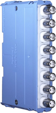
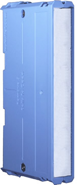
i51x wiring boxes easily bolt to i4xx cards. The i510 is the simplest and is included with the i555 starter system. The i511 includes 8 bnc connectors. The i512 has a vRef/2 source that is used to help complete 1/4 bridge and 1/2 bridge strain gage circuits. If you are measuring thermocouples, then the i510 is the only wiring box that will work, since it contains an internal temperature sensor that measures the temperature of the i510 screw terminals.
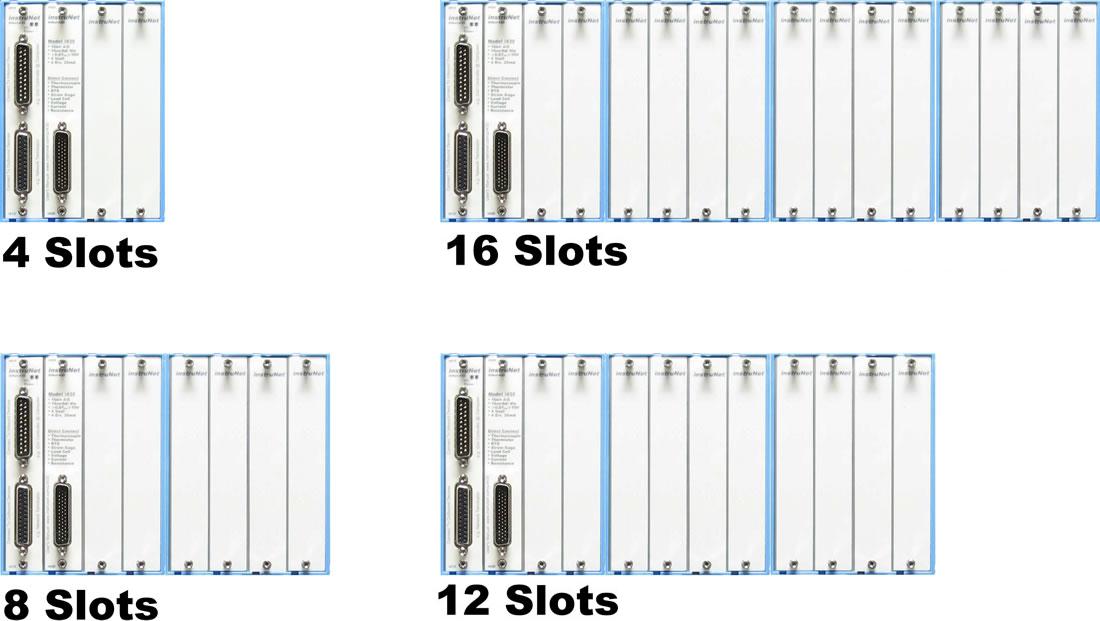
Low Cost 4/8/12/16 Slot Card Cage The i400 product provides 4 slots, and multiple i400's can be bolted together by the end user, side-by-side, to create an 8, 12, or 16 slot system. In many applications, one i400 with 4 slots is sufficient.
iNET-400
STARTER SYSTEM
i4xx CARDS
i4xx CARD CAGE
ACCESSORIES
Mr. G. Weinreb
instrunet, data acquisition, data acquisition system,data acquisition card, pci data acquisition, data acquisition software, data acquisition boards, pcmcia data acquisition, PC-based data acquisition, PC data acquisition, data acquisition hardware, data acquisition, data acquisition, thermocouple, thermocouple amplifier, thermocouple meter, thermocouple signal condition, thermocouple measurement, thermistor, thermocouple amplifier, thermistor meter, thermistor measurement, thermistor signal condition, strain gage, strain gage amplifier, strain gage meter, strain gage measurement, strain gage signal condition, RTD, RTD amplifier, RTD meter, RTD measurement, RTD signal condition, 0-20mA, 0-20mA amplifier, 0-20mA meter, 0-20mA measurement, 0-20mA signal condition, resistance meter, resistance measurement, volt meter, voltage measurement, current meter, current measurement, isolated signal condition, A/D board, A/D card, analog to digital converter, A/D converter, a/d, analog-to-digital, analog-to-digital converter, digitize, digitize waveform, digitize waveform with a/d, dasylab, data translation, iotech, adac, metrabyte, gw instruments, glenn weinreb, windows, windows xp thermocouple, thermocouples, thermocouple sensor, thermocouple measurement, j thermocouple, k thermocouple, t thermocouple, e thermocouple, r thermocouple, s thermocouple, b thermocouple, n thermocouple, instrunet, data acquisition, data acquisition system,pci data acquisition, data acquisition card, signal conditioner, amplifier, thermocouple meter, thermocouple supplier, thermocouple manufacturer, thermocouple store, thermocouple amplifier, thermocouple measurement, instrunet, gw instruments, windows, windows xp, excel, dasylab, labview thermistor, thermistors, thermistor sensor, thermistor measurement, ysi thermistor, 2252 thermistor, 40xxx series thermistor, 10000 thermistor, 10K ohm thermistor, precision thermistor, instrunet, data acquisition, data acquisition system,pci data acquisition, data acquisition card, signal conditioner, amplifier, thermistor meter, thermistor supplier, thermistor manufacturer, thermistor store, thermistor amplifier, temperature measurement, instrunet, gw instruments, windows, windows xp, excel, dasylab, labview strain gage, strain gages, strain gage, strain gages, strain gage sensor, strain gage measurement, 120 ohm strain gage, 350 ohm strain gage, load cell strain gage, precision strain gage, ¼ Bridge strain gage, ½ Bridge strain gage, full bridge strain gage, axial strain gage, instrunet, data acquisition, data acquisition system,pci data acquisition, data acquisition card, signal conditioner, amplifier, strain gage meter, strain gage supplier, strain gage manufacturer, strain gage store, force measurement, force sensor, strain gage amplifier, strain gage measurement, instrunet, gw instruments, windows, windows xp, excel, dasylab, labview quadrature, quadratures, quadrature sensor, quadrature measurement, linear quadrature, radial quadrature, and many other precision quadrature sensor types, instrunet, data acquisition, data acquisition system,pci data acquisition, data acquisition card, signal conditioner, amplifier, quadrature meter, quadrature supplier, quadrature manufacturer, quadrature store, quadrature amplifier, instrunet, gw instruments, windows, windows xp, excel, dasylab, labview load cell, load cells, load cell sensor, load cell measurement, 120 ohm load cell, 350 ohm load cell, 1000 ohm load cell, precision load cell, instrunet, data acquisition, data acquisition system,pci data acquisition, data acquisition card, signal conditioner, amplifier, load cell meter, load cell supplier, load cell manufacturer, load cell store, force measurement, force sensor, load cell amplifier, load cell measurement, instrunet, gw instruments, windows, windows xp LabVIEW, LabVIEW software, LabVIEW data acquisition, LabVIEW hardware, LabVIEW and ni, instrunet, data acquisition, data acquisition system, pci data acquisition, data acquisition card, LabVIEW a/d board, LabVIEW boards, LabVIEW and national instruments, LabVIEW and instruNet, MeasX, National Instruments, datalog, dasytec, instrunet, gw instruments, windows, windows xp data logger, PC-based data logger, data loggers, data logger, PC data logger, pc-based data logger, pc data logger, data logger systems, data logger hardware, data logger software, data logger card, data logger board, thermocouple, thermocouple amplifier, thermocouple meter, thermocouple signal condition, thermocouple measurement, thermistor, thermocouple amplifier, thermistor meter, thermistor measurement, thermistor signal condition, strain gage, strain gage amplifier, strain gage meter, strain gage measurement, strain gage signal condition, RTD, RTD amplifier, RTD meter, RTD measurement, RTD signal condition, 0-20mA, 0-20mA amplifier, 0-20mA meter, 0-20mA measurement, 0-20mA signal condition, resistance meter, resistance measurement, volt meter, voltage measurement, current meter, current measurement, isolated signal condition, A/D board, A/D card, analog to digital converter, A/D converter, a/d, analog-to-digital, analog-to-digital converter, digitize, digitize waveform, digitize waveform with a/d, dasylab, data translation, iotech, adac, metrabyte, gw instruments, glenn weinreb, windows, windows xp instrunet, data acquisition, data acquisition system,data acquisition card, pci data acquisition, data acquisition software, data acquisition boards, pcmcia data acquisition, PC-based data acquisition, PC data acquisition, data acquisition hardware, data acquisition, data acquisition, thermocouple, thermocouple amplifier, thermocouple meter, thermocouple signal condition, thermocouple measurement, thermistor, thermocouple amplifier, thermistor meter, thermistor measurement, thermistor signal condition, strain gage, strain gage amplifier, strain gage meter, strain gage measurement, strain gage signal condition, RTD, RTD amplifier, RTD meter, RTD measurement, RTD signal condition, 0-20mA, 0-20mA amplifier, 0-20mA meter, 0-20mA measurement, 0-20mA signal condition, resistance meter, resistance measurement, volt meter, voltage measurement, current meter, current measurement, isolated signal condition, A/D board, A/D card, analog to digital converter, A/D converter, a/d, analog-to-digital, analog-to-digital converter, digitize, digitize waveform, digitize waveform with a/d, dasylab, data translation, iotech, adac, metrabyte, gw instruments, glenn weinreb, windows, windows xp |
||||||||||||||||||||||||||||||||||||||||||||||||||||||||||||||||||||||||||||||||||||||||||||||||||||||||||||||||||||||||||||||||||||||||||||||||||||||||||||||||||||||||||||||||||||||||||||||||||||||||||||||||||||||||||||||||||||||||||||||||||||||||||||||||||||||||||||||||||||||||||||||||

